Modbus Rtu Wiring Diagram
1 von 10 modbus tcp/ip tcp port: Figure 3 wj102 wiring diagram power supply wiring diagram wiring explanation use pin1, pin2 screw terminals to connect the power supply.

Modbus 485 Wiring Diagram Wiring Diagram
Reset jumper jp1 acts as a reset switch for each individual rtu board.

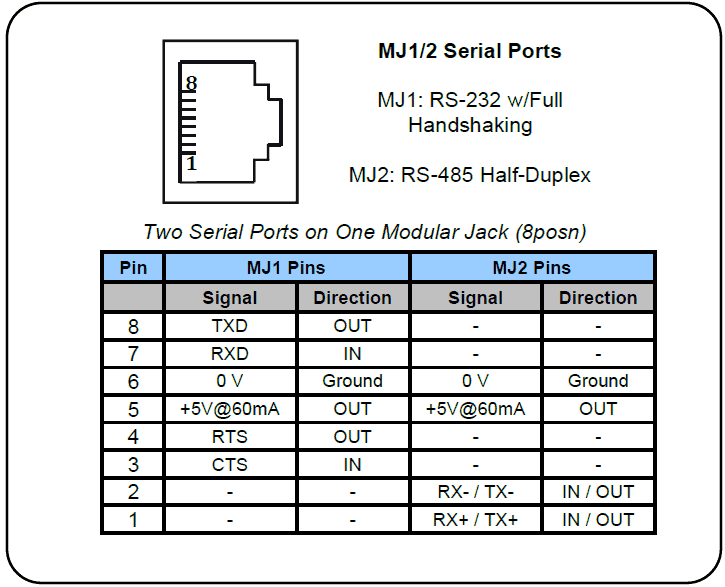
Modbus rtu wiring diagram. 8.6 modbus rtu overview 136 8.6.1 assumptions 136 8.6.2 what the user should already know 136 8.6.3 modbus rtu overview 136 8.6.4 frequency converter with modbus rtu 137 8.7 network configuration 137 8.8 modbus rtu message framing structure 137 8.8.1 frequency converter with modbus rtu 137 8.8.2 modbus rtu message structure 137 8.8.3 start/stop. Rj45 connector (diagram 1 ~ diagram 6) diagram 1 cmt series cmt3151 emt series emt3070/ emt3105 / emt3120 / emt3150 hmi plc com1 com3 rs485 2w rs485 2w 8 p rj45 9p male. Cable termination (rs485/modbus rtu line bias) overview.
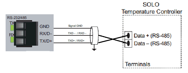
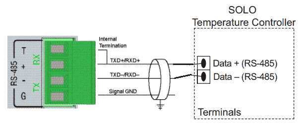
Wiring diagram of the serial rs232/rs485. Schneider modbus rtu controller (m221). After restore factory setting, if required using modbus rtu to modbus tcp, we need to set the baud rate of ttl1 entry, the local port and work mode.
Wiring for n2 ms tp or modbus rtu protocol metasys part no 24 10143 63 supervisory device network engine 9 0 7. The wiring of modbus rtu / rs485 is to be carried out in accordance with applicable directives (www.modbus.org). Modbus communication wiring diagram for conversion of rs 485 2 wire to 4 automation plc programming scada pid control system.
M bus to modbus converter viltrus. Data flow is restricted, i.e. Modbus rtu and ascii protocols are supported over rs232 and rs485.
Modbus wiring should be selected such that the characteristic ac impedance (z _) of the cable matches the impedance of standard transceiver chips. 3.1 modbus rtu protocol modbus rtu is the only supported transmission mode. Several cables and wiring methods are referenced by installers when deploying modbus communications networks.
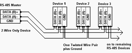
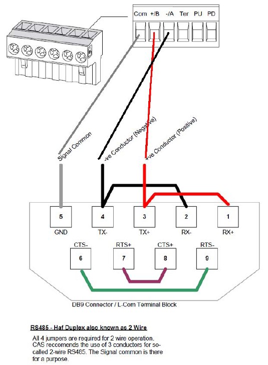
If it isn't practical to wire from master to slave 1 to slave 2 to slave 3 in a daisy chain, then your diagram looks ok to me. Modbus ascii mode is not supported. Engineers at deck monitoring have reviewed information from many sources to create the following recommendations for a standard and robust wiring method.
+8~32vdc wide power supply range. Modbus recommends awg 24 cable. General information about modbus for exchange of information among automation systems and the connected decentralised field devices, the use of serial fieldbus systems for communication is.
Modbus also recommends a characteristic impedance with a value higher than 100 ohms for the balanced pairs used. Perform wiring for the programmable controller power cable, the servo amplifier power cable, the servo motor power cable, the encoder cable, the communication cable, and the. Rs232 ports are commonly used for interfacing hmi and other devices through modbus rtu communications.
Schneider modbus rtu supported series : Modbus over serial line cable must be shielded. Modbus protocol description drawing no.:
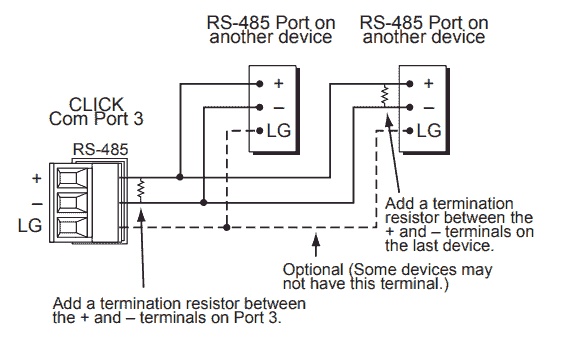
They are also commonly used to interface cellular transceivers for internet of things applications and can be used in ascii communications. There should probably be a terminating resistor at the master. Be sure to read through instruction manual for the actual wiring.
The wiring diagram in this section is a schematic. When add a new 3rd party device using modbus rtu or ascii all configuration fields are required, with the exception of the notes free text field. The device possesses resistors which can be switched on for bus
Certain ace have rs232 ports or configurable rs232/485 ports. Configuration options must be set correctly based on the configuration of the connected modbus server(s). Transmit and receive cannot be simultaneous (half duplex).
Ac 01.2/acexc 01.2 modbus rtu safety instructions. Rs485 modbus connection tcp ip rtu diagram rs 485 9 rules for correct cabling of the communication systems wiring from a 172jnn21032 port 2 rj45 to an lulc031 interface faqs schneider electric hungary beckhoff information system english 4 120 53 mmunication module n2 ms tp or protocol metasys part no 24 10143 63. At the physical level, modbus over serial line systems may use different physical interfaces (rs485, rs232).
Modbus RTU BRX PLC Master to Click PLC Slave Communication Acc Automation

Modbus RTU Master DAT9000
Rules to do perfect cabling of MODBUS RTU RS485 communication systems TrackSoSolar PV
ModBus RTU communication between Omron CP1E (CP1WCIF11) and an Arduino using MAX485 RS485


Modbus RTU Master with Analog IO DAT9011
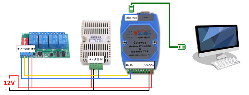
OZEKI Devices / Masters Modbus RTU/TCP gateway (Volison)
Horner XL4 Modbus RTU Instructions Acc Automation

Modbus Rtu Wiring Diagram Sample

Modbus Rtu Wiring Diagram Sample
DATA Logging RS485 Modbus DAT9000DLIO with Digital IO

Modbus to converter and gateway for Modbus RTU.


Modbus Rtu Wiring Diagram Sample
BRX PLC Serial Communication Modbus RTU to Solo Process Temperature Controller Acc Automation
Productivity 1000 Series PLC Modbus RTU Serial Communication Acc Automation

ᗖR421C32 DC 12V 32 Channels Modbus RTU RS485 Bus Relay Module UART Serial port Board for PLC LED

Modbus Rtu Wiring
Modbus RTU to Metasys N2 Configuration Sample Chipkin Automation Systems
Modbus Rs485 Wiring Diagram My Wiring DIagram

Modbus Rtu Wiring Diagram Sample

